Baby Pac-man restoration log
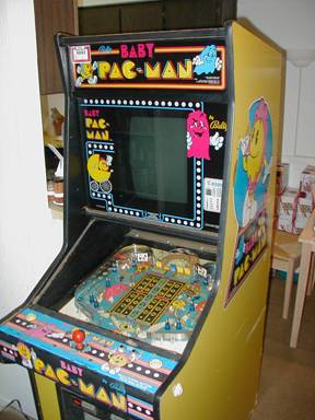 |
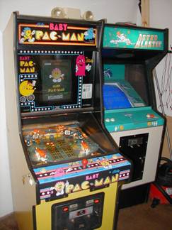
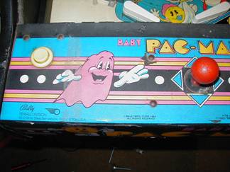
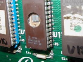
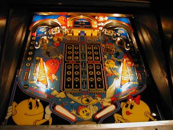
I got the unit today, and I have to admit, I didn’t expect the game to be in such bad condition. There are cracks and chips and holes, oh my. The unit is pretty dirty, and the playfield needs lots of work. Never mind that the unit does not come up at all. So I started with the game electronics to see if I could get them to come up with at least some self test data. Unfortunately, this was not to be so. So I break out the manual and schematics and start from there. The MPU module LED was constantly on, and the VIDEOT board LED quit flashing after the 4th flash. I burned a new EPROM for the VIDEOT board U10 (as the self test LED indicated) with no success after installing it in it’s socket. I probed around the pins of the EPROM and everything looked O.K., but I was not convinced – so I installed a new socket at U10, and BINGO!!! The VIDEOT board gave all 11 flashes, meaning it was ready to take instructions from the MPU.
|
 |
|
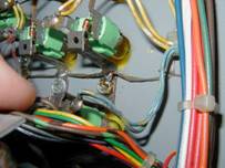
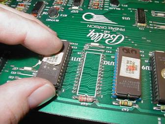
| I was looking at the MPU board and noticed that it had only 1 EPROM installed in 1 of 3 sockets. Missing EPROMS!!! I was able to get the images on newsgroups (only to find out later that they were available at the WMS pinball site, with other cool data that’s coming up). So I was ready to burn a new EPROM, but it seems that they had a 2532 EPROM installed. All I had in stock were 2732, and they are not pin-for-pin compatible. Luckily the EPROM images from the WMS file contained a jumper list to convert the board to take 2732’s. So after doing some rework on the board, and other investigative work (it seems that the MPU board does not use the U1 socket when 2532/2732s are installed. It was meant for the scenario of two 2516/2716s being installed). All done! Install the board, get the correct number of LED flashes, but NADA! Nothing on the screen. | 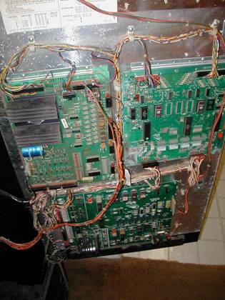 |
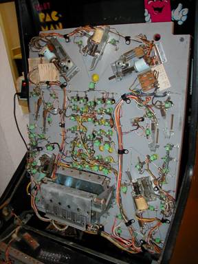
I was able to get the system to go into the communications test, and there were problems indicated. I needed a break from the boards for awhile, so I moved over to the playfield. I removed the playfield plastics for cleaning. The rubbers were so far gone that you could smell the rot (I could actually smell this while it first arrived in the crate!). I’m afraid to touch the playfield with anything until I get the wildcat and Novus 3 polishes that I have read so much about. On the underside of the playfield, there were several burned coils, on that had been disconnected by previously, and the coil was burned completely BLACK! So I removed the bad coils, and readjusted the switches, etc. I will have to order a lot of parts………….
|
|
| Time to tackle that MPU communication problem! Since the boards had the usual corrosion from the NiCd battery mounted on the MPU, I decided to replace the headers on the MPU. No change, but I did notice some rework in the area near the communications connection. After checking the schematics, it seems that the previous owner attempted to repair the board (might I add, unfortunately, in many places!) and soldered a 4.7K resistor where a 470 ohm resistor should have been. BINGO! The communications test now shows the proper data, but still won’t boot to the game screen. After some time to pull back and brainstorm, I remembered that other Bally/Midway games had a freeze switch in the DIP banks, so checked, and all the DIPS were turned “On”. I turned them all off, and YIPPIE!!!! Game screen!!!!! The monitor looks pretty distorted though, so I will order a cap kit from Bob Roberts. | 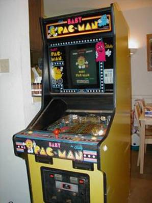 |
There’s no sound, so I checked what was coming out of the DAC on the VIDEOT board, and it was O.K., so it must be the amplifier. Ordered that chip from Bob Roberts as well. I also ordered all (well, most of) the parts I need from Marco Specialties.
|
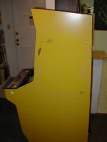 |
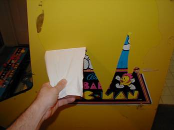
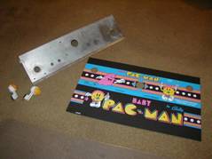
I decided to order a control panel overlay from Arcade Renovations today. Also new T-molding from T-molding.com. I decided to not order the side art until a later date. I removed one of the old side art decals from the cabinet side – it’s kind of therapeutic. It takes patience, and getting it off in large sheets is almost as fun as the game will be when it’s playable. Alcohol works well to remove the adhesive left behind.
|
 |
|
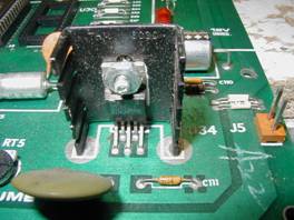
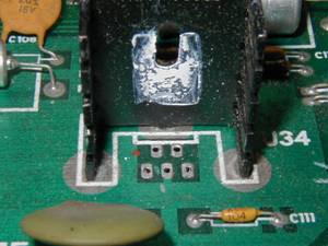
The Marco parts came in, so I’ll have flippers and coils and kickers and balls……. First to go in was the coils.. I did not know that the coils from Marco would come with new sleeves, so I now know better than to order them separate like I did this time. Oh well, so now I have some spares. I replaced one of the transistors for the left saucer kicker, as it was shorted internally, and probably caused the blackening of the coil that was there.
|
 |
||
 |
All-new lamps were installed, and the underside of the light caps cleaned with a swab. MANY non-working lamps, and lamps that were stuck in the “On” state were found when the machine was plugged in. After doing some checking of the lamp SCRs with a meter, it did not seem as if they were shorted out. So out came the Solenoid/Lamp driver board. There were several of the pins on the lamp connectors that had obvious cold and cracked solder joints, as well as some pins that were half-broken off.
|
 |
|
|
So after some rework and replacement of the headers, I plugged it back in and it got rid of the “Always on” syndrome. But there were still some lamps that were not coming on at all. After playing around with the lamps and sockets, I realized that there were COLD JOINTS at the connections to the bus wire. It did explain the failure to light in pairs, as there were sockets that used a single piece of metal for mounting 2 lamps. Re-soldered those suckers, and everything lights up perfect. I installed new locks on the coin and rear doors, but the 4th lock I ordered was for the control panel lockdown bar, and the lock wasn’t long enough. I need to get my hands on a 1 ¼” cam lock…. Home Depot maybe? Now I’m waiting on playfield rubber, a new control panel overlay from Arcade Restorations, and some coin acceptors from an e-bay purchase (read the auctions carefully – this guy wanted an international money order, as he was in Canada, and he did not take pay-pal. This added $3.50 to the merchandise and shipping, never mind the 60 cents to mail it to him!!!! WHAT A RIP!!) I also need the playfield glass, and will check the prices for tempered. I’m off to Home Depot to see if they have a lock and a temporary piece of playfield glass. UPDATE: Home depot only carried window glass, nothing close to 3/16” thick. Just heard from Bob Roberts, and the Monitor Cap Kit and Audio Amp chip should be here Saturday. |
|||
|
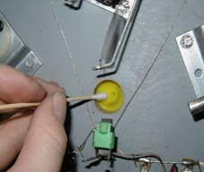
Today is the day to strip the control panel down to bare metal so that the new overlay does not sit on rust. It’s in pretty nasty shape! When I peeled the CPL overlay off, it left behind a thick
layer of black adhesive/paper. I found
that using one section of a break-off cutter blade in a vise-grip worked
great! If the blade was wider, it would
have been too difficult to scrape the adhesive layer off. |
 |
||
 |
When the bulk of the solid adhesive was gone, the panel was still very sticky. This was cured by using trusty ole’ Ronsonol lighter fluid to literally ‘melt’ the adhesive residue away. Just lay down a layer of the fluid, let it sit for 30 seconds, then use a putty knife to scrape around. | 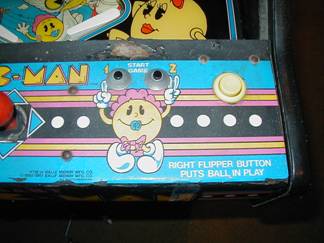 |
|
| Soon, you’ll have a goopy mess of fluid soaked adhesive on the panel. Paper towels are ideal here, since as soon as the fluid evaporates the adhesive gets wicked sticky again. So scrape the goop on the paper towels, and repeat one more time. | 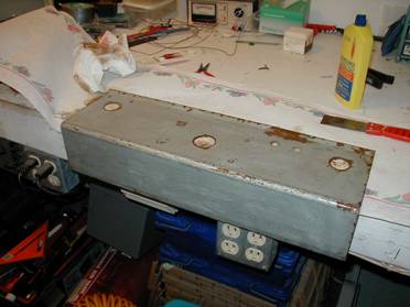 |
For the last step, just wet a wad of paper towel with the lighter fluid, and wipe down the panel. This will remove any last traces of that STUBBORN adhesive. After sanding with an orbital sander and some 200 grit, the panel comes out shiny and gorgeous.
|
|
 |
I’ve read on other sites that people spray primer on the metal before applying the new overlay….. I’m still debating as to do this or not, since originally the metal was not primed. I know that it will prevent rust, but unless the CPL overlay had shrank, there was a small band of metal exposed around the joystick hole. Decisions, decisions… I also reworked the Videot again, as U10 started to show signs of being flaky, and I wanted to remove the TDA-2002 audio amp chip in preparation for the new chip to arrive tomorrow.
|
 |
|
 |
 |
 |
|
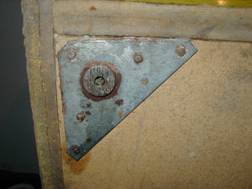 |
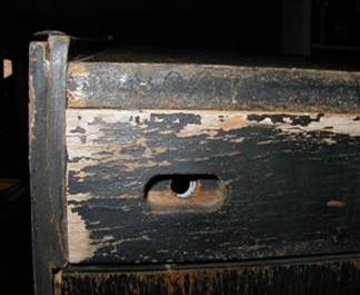
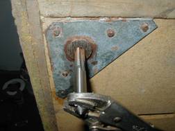
The cap kit and audio amp came in. I also decided to install new leg levelers on the front, as the machine came with them missing. As
you can see, the threaded hole for the leveler was pretty full of crud, and had
to be tapped out. Then the leveler could
be screwed in quite easily.
|
 |
| The audio amp went in next, and voila! SOUND!!! | 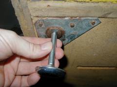 |
|
|
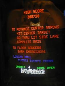
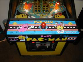
The monitor was next on the hit list, and needed a capping since the picture was squished and distorted. You can see this by the slope of the “High Score” words.
|
 |
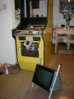
So out the monitor came.
There were 2 ways to remove it:
Or
Going with #2 since I didn’t want to balance a heavy, yet delicate monitor while trying to fiddle with bolts and nuts……..
|
 |
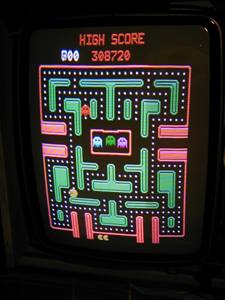
While I was replacing all the caps on my G07-FBO monitor, I noticed that the document that came with the cap kit had two cap values reversed (C517 & C518). I looked at the schematics, and verified on the board that it was non critical, since the two caps are connected in parallel anyway…… All finished…. Now there’s no more squish, and the picture is bright and stable!
|
 |
 |
The rubbers came in, and boy am I confused! I have no idea how the set is supposed to go onto the playfield. The diagram in the manual is useless, so I install them the best I can using my mind-reading mental power. And for the first time, the playfield is complete with plastics and lighting……..
|
|
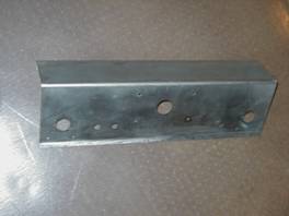
| So, while waiting for the control panel overlay, I decided to hunt for new carriage bolts, but nobody had them in stock locally. I decided to restore what I had. As you can see, they’re pretty corroded. | 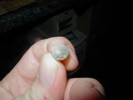 |
|
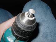 |
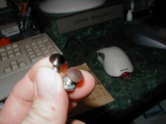
Here’s what I did to restore: 1) Mount the bolt in a drill chuck. 2) Start the drill. 3) Apply sandpaper to spinning head. 4) Apply black sharpie pen. You can see the difference, eh???
|
 |
| What a fiasco! My playfield glass came in today, and it seemed a bit heavy to me… After getting it home, the shipping paper comes off and – 3/8” glass!!! - &*(%#&(@*. I KNOW I ordered 3/16”. Since this is tempered, they would not let me take it back. $80.00 down the drain… | 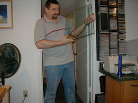 |
But here’s the real kicker – a piece of 3/16” tempered is only $16.00
– DOH!!!! So what… I’ll make myself a pity shelf from the unusable glass…. Something to be bitter about hanging on the wall ;) |
 |
The control panel overlay came in today! Well, sort of…. UPS SUCKS! Turned out the tracking information didn’t match where the package was (term “lost” comes to mind). Two trips to the UPS package counter later, I had it in my hand… |  |
| Thinking about how best to center it on the metal panel for installation, I found that using the carriage bolts in 2 places worked best. |  |
After wrestling with this thing for a good 10 minutes, all is well and the world is peaceful again! |
4/2/04
Here is some information about h
1)
Turn the Red, Green, and Blue trimmers fully counterclockwise.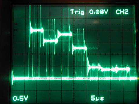
2) Connect channel 2 of the scope to the sync pin on the Videot.
3) Connect channel 1 of the scope to the Green pin on the Videot.
4) Set the scope for triggering from channel 2, and set controls as follows;
Ch1: 0.5v/div, Ch2: 2v/div, 5us/div.
5) Press the Video Test button on the Videot board twice (to produce color bars).
6) Align the floor of the signal with one of the lower lines of the graticule using the V-position on the scope, and adjust the Green trimmer on the Videot so that the first peak line lays on the 4th line up from the floor on the graticule (2v p-p) as shown in the picture.
7) Move the channel 1 probe to the Blue pin, and adjust so that the same result is obtained.
8) Move the channel 1 probe to the Red pin, and adjust so that the same result is obtained.
9) You will notice that if the red or blue trimmer is too high, the floor level will rise at a certain point. If so, adjust it back down to a stable floor.
10) If the picture on the monitor is not stable, rotate the Sync trimmer on the Videot board until stable.
11) Adjusting the monitor using the method in the owner’s manual should result in perfect colors, and a low-noise picture.