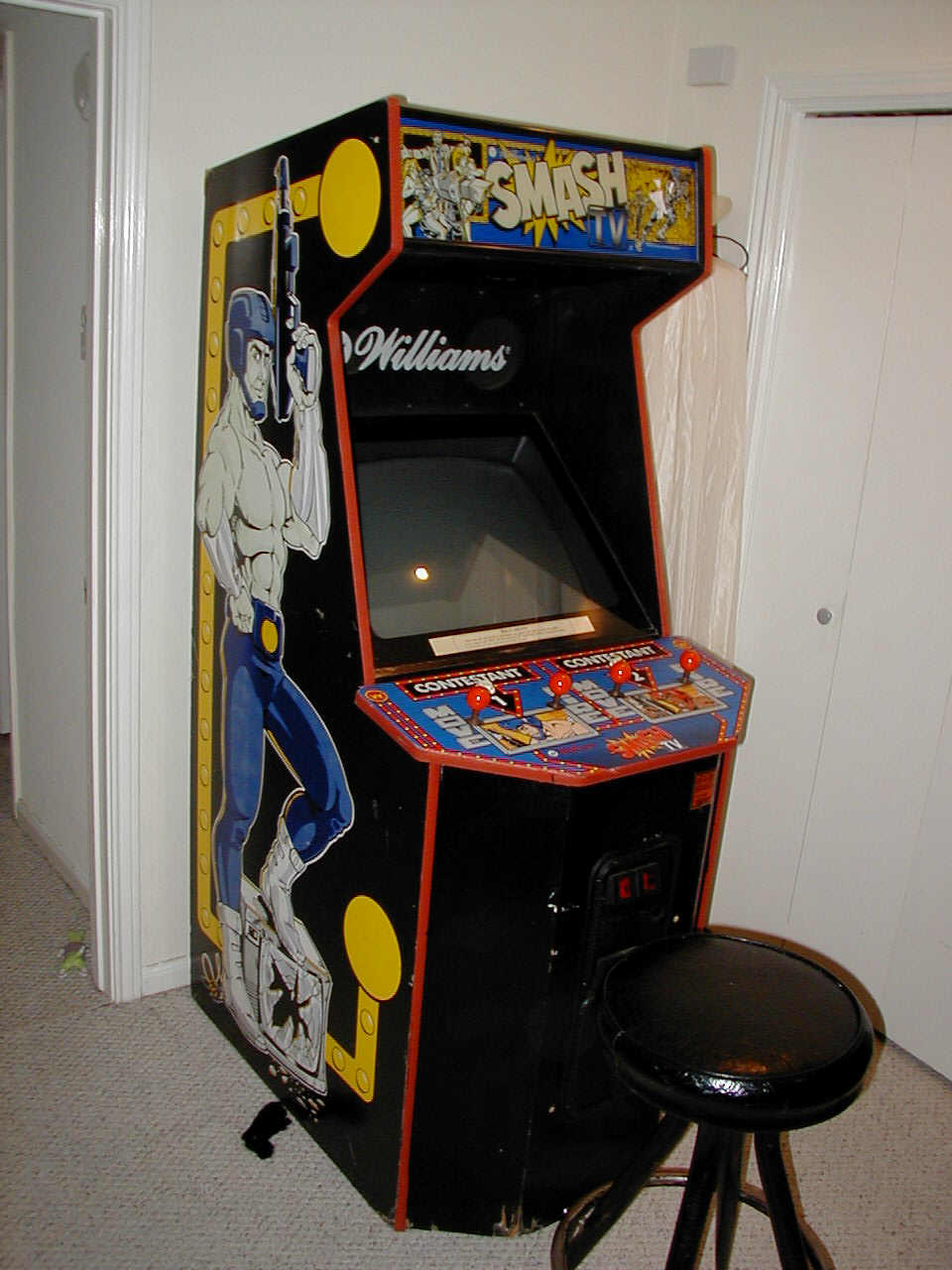
The MAME Cabinet started out as a Williams Smash TV. I picked it from an auction in Dallas, TX in December 2002, mostly because of the larger monitor (25") and the large control panel area. The side art did not hurt, either.
The first things to get changed were the speaker grille & marquee. The big , white "Williams" logo was easy enough change by simply flipping the grille over. The mounting holes mirrored perfectly. The marquee was a little harder.
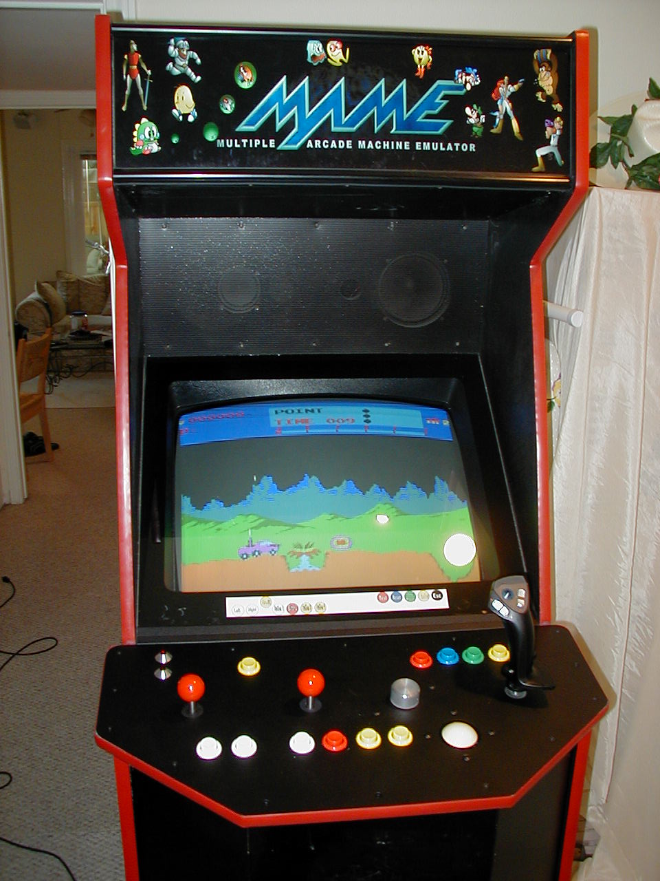
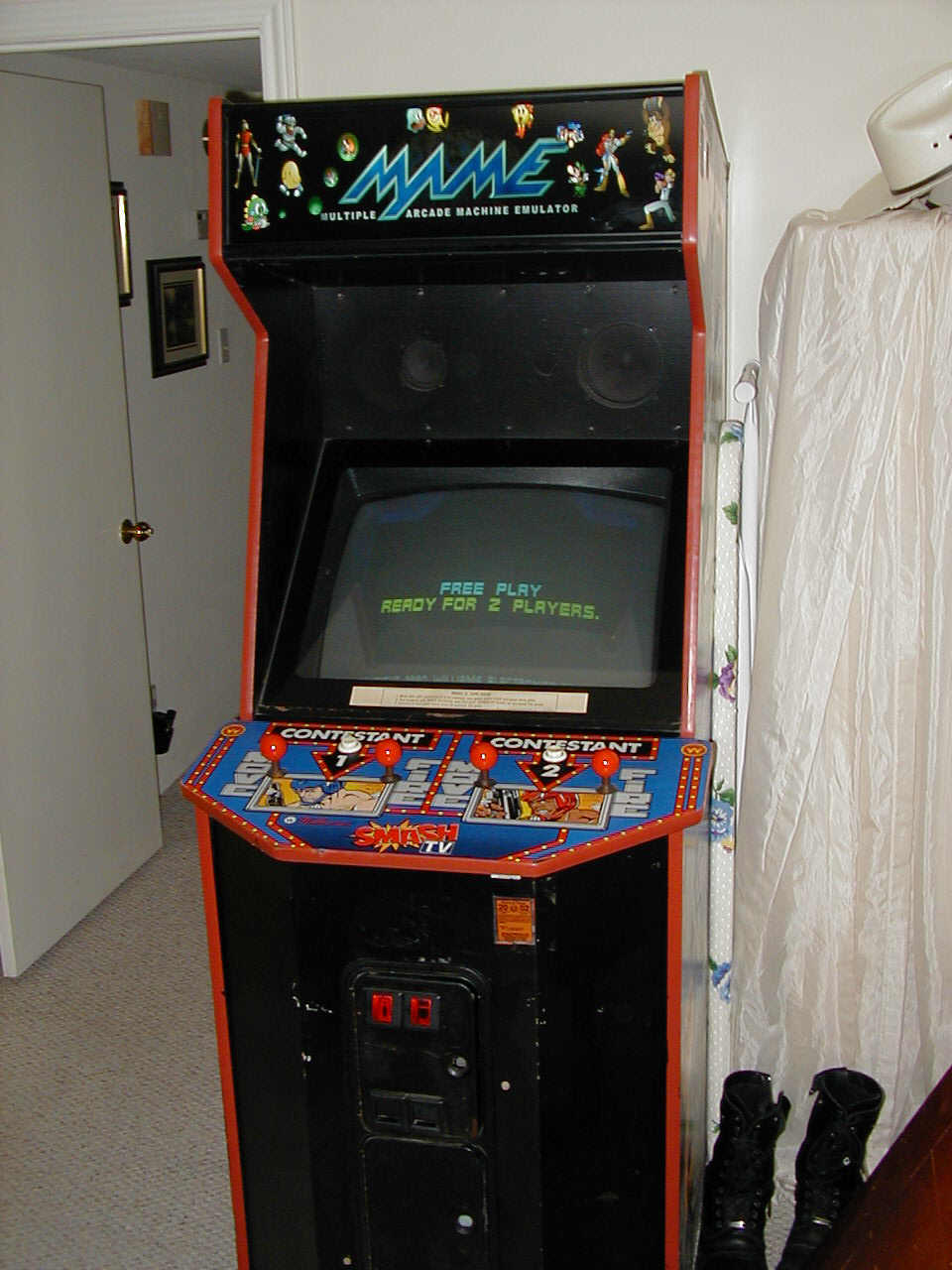
I found a nice, printed marquee for MAME on E-bay. I ordered 2 pieces of glass, one for the front, and one for the back, and sandwiched the marquee between the two. The only difficult part was making careful measurements so that the glass fit properly - since it is made from tempered glass, getting it right the first time was important.
You can get the same MAME Marquee used here from EMDKAY Marquees

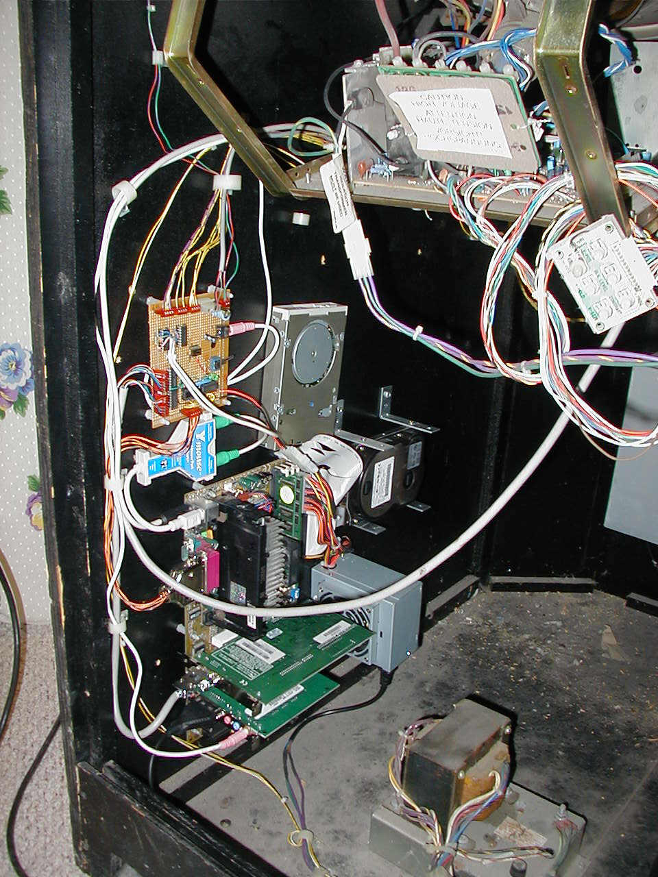
The next thing to do was install the PC hardware and interface boards. I installed a P3-450 with a 5GB hard drive. I also built an interface board that includes circuitry for isolating the arcade monitor from the VGA outputs until turned on by the program, as well as PS/2 mouse inputs and a sound amplifier.
The video isolation uses CMOS 4066 bilateral switches for each of the video signals (Red, Green, Blue, V-sync & H-sync). It is turned on and off using the parallel port. Some NAND gates decode a specific bit pattern from the port outputs, and activate the switches. A simple DOS C program was written that sets/resets the port, and could be called from a batch file or ArcadeOS.
The dual mouse circuits were included on the perfboard to interface a spinner for games like "Tempest" and "Tron", and a trackball for "Centipede" and others. A "Y-Mouse" adapter was used to connect both mouse circuits to the single PS/2 connector on the motherboard.
The sound amplifier uses a simple LM384 amp chip, and is configured as a summing amp for the left and right channels, since the cabinet only had one speaker.
I installed ArcadeOS as the front-end interface to select games, and choose AdvanceMAME for the emulator, since it handles translation of vertical games to horizontal displays better than DOS MAME, which only uses standard VESA video modes.
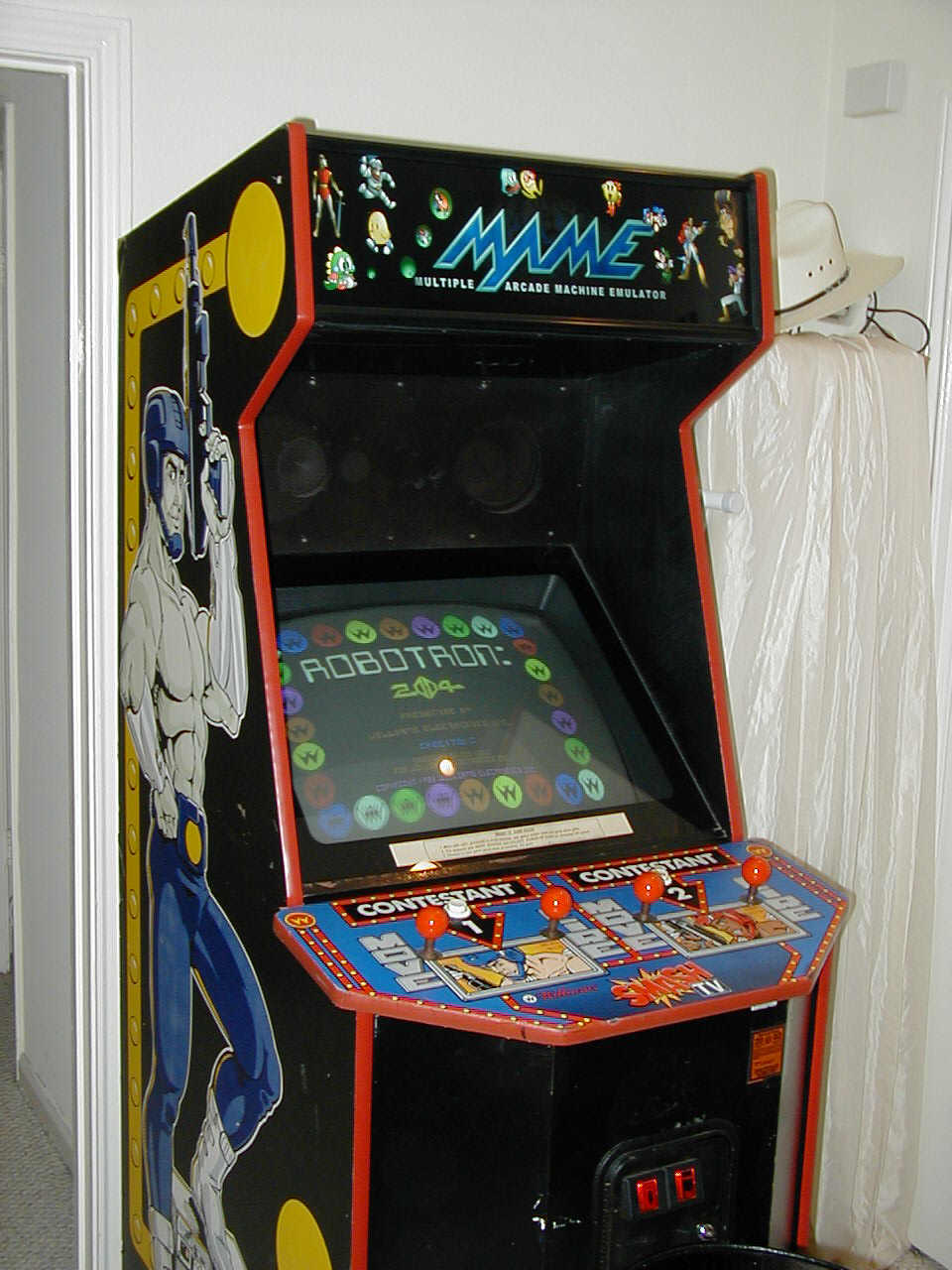
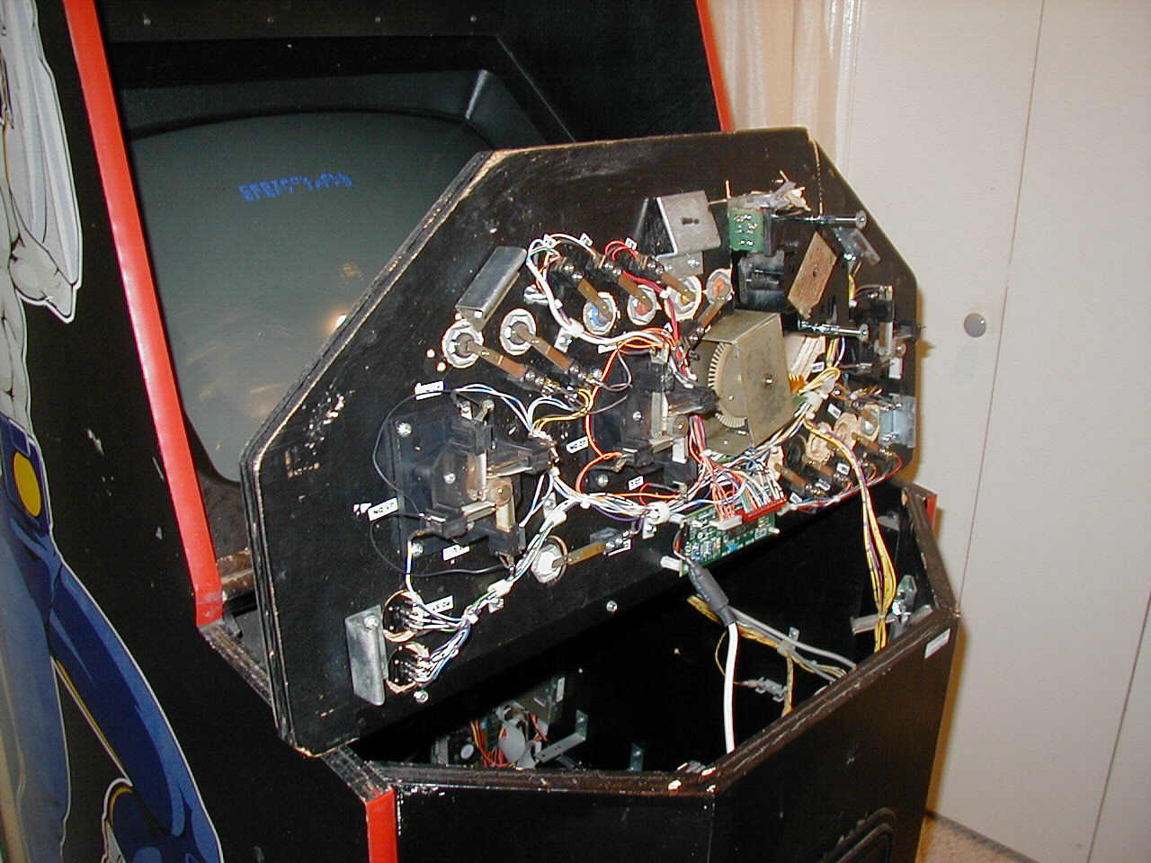
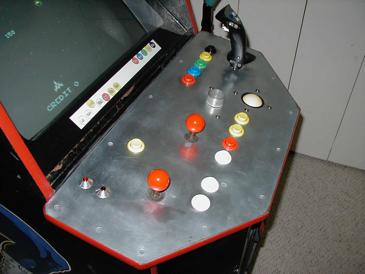
The control panel was next. I wanted to keep the "Dual Sticks" for games like "Robotron" and "Krull", so I left 2 sticks in place, and had to decide where to place the remaining controls.
One of the old Joystick holes worked well for a spinner, and the other available hole would work for the trigger handle joystick. I used this configuration to figure out where the buttons and trackball would fit.
I printed out discs of CD-label stock the same size as the controls to "place" everything. This allowed me to change the layout before drilling any holes.
The original Williams panel consists of sheet metal over a 3/4" plywood. This presented a problem when mounting the spinner and trackball, which are designed for sheet metal installations.
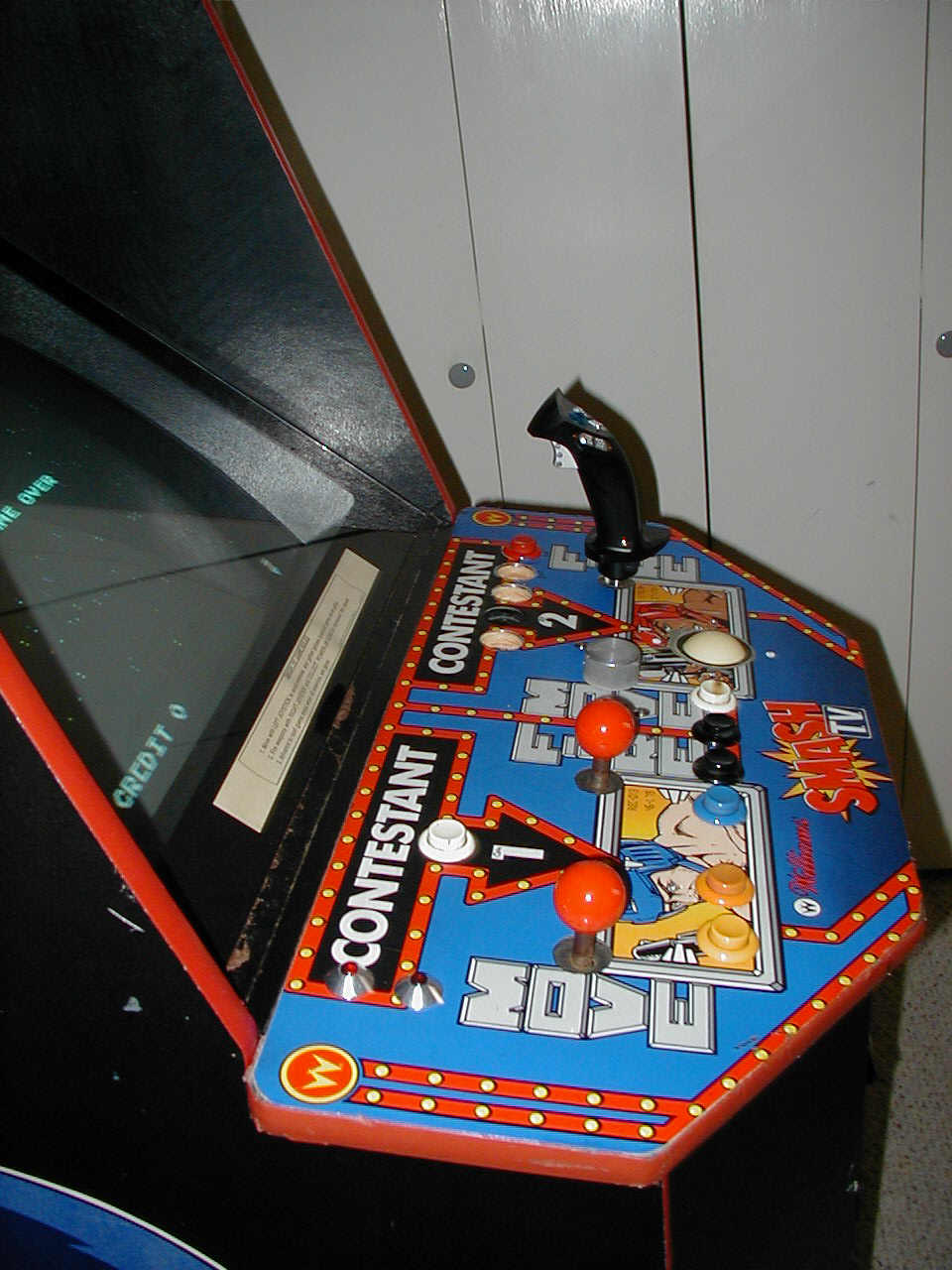
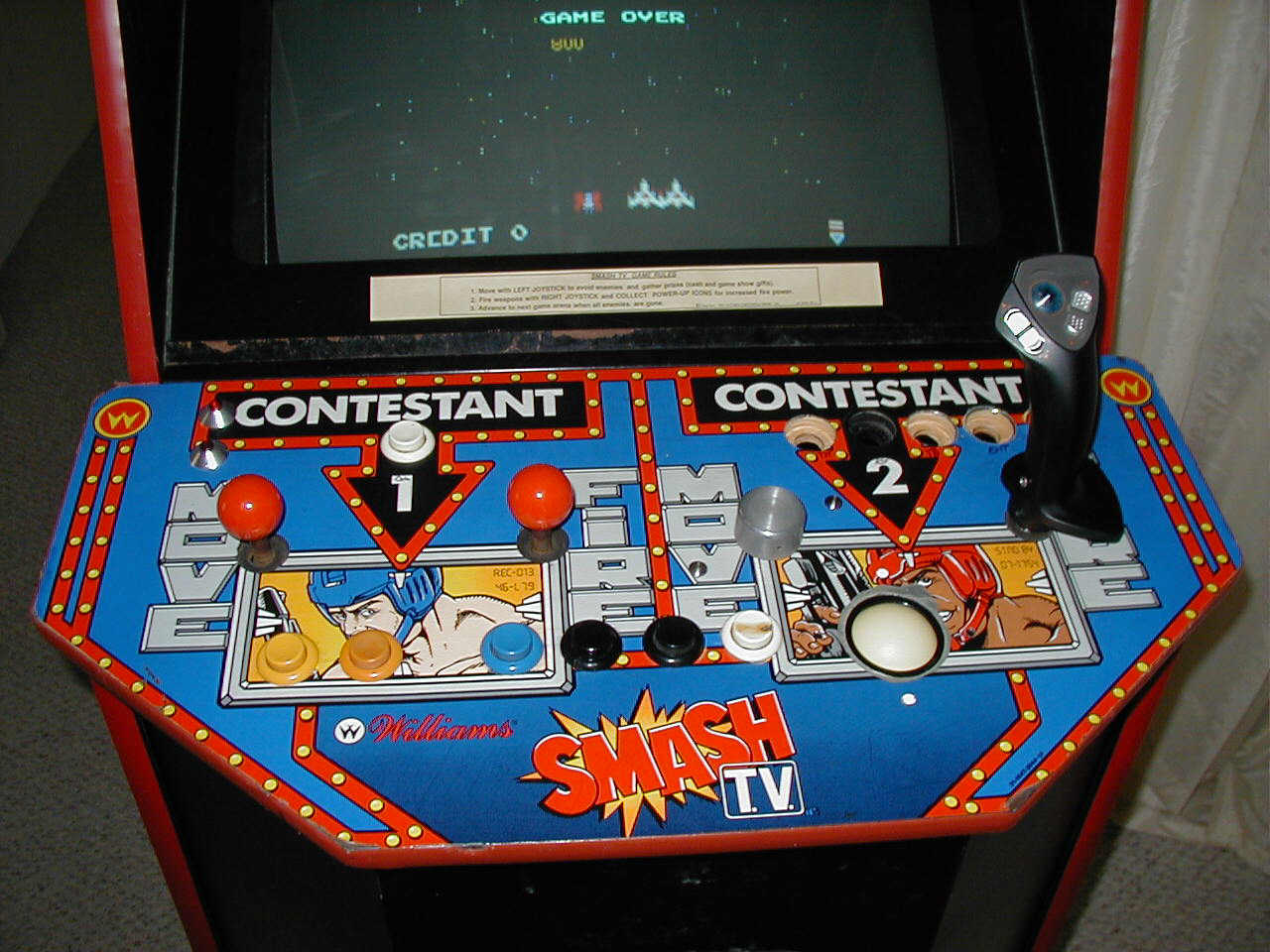
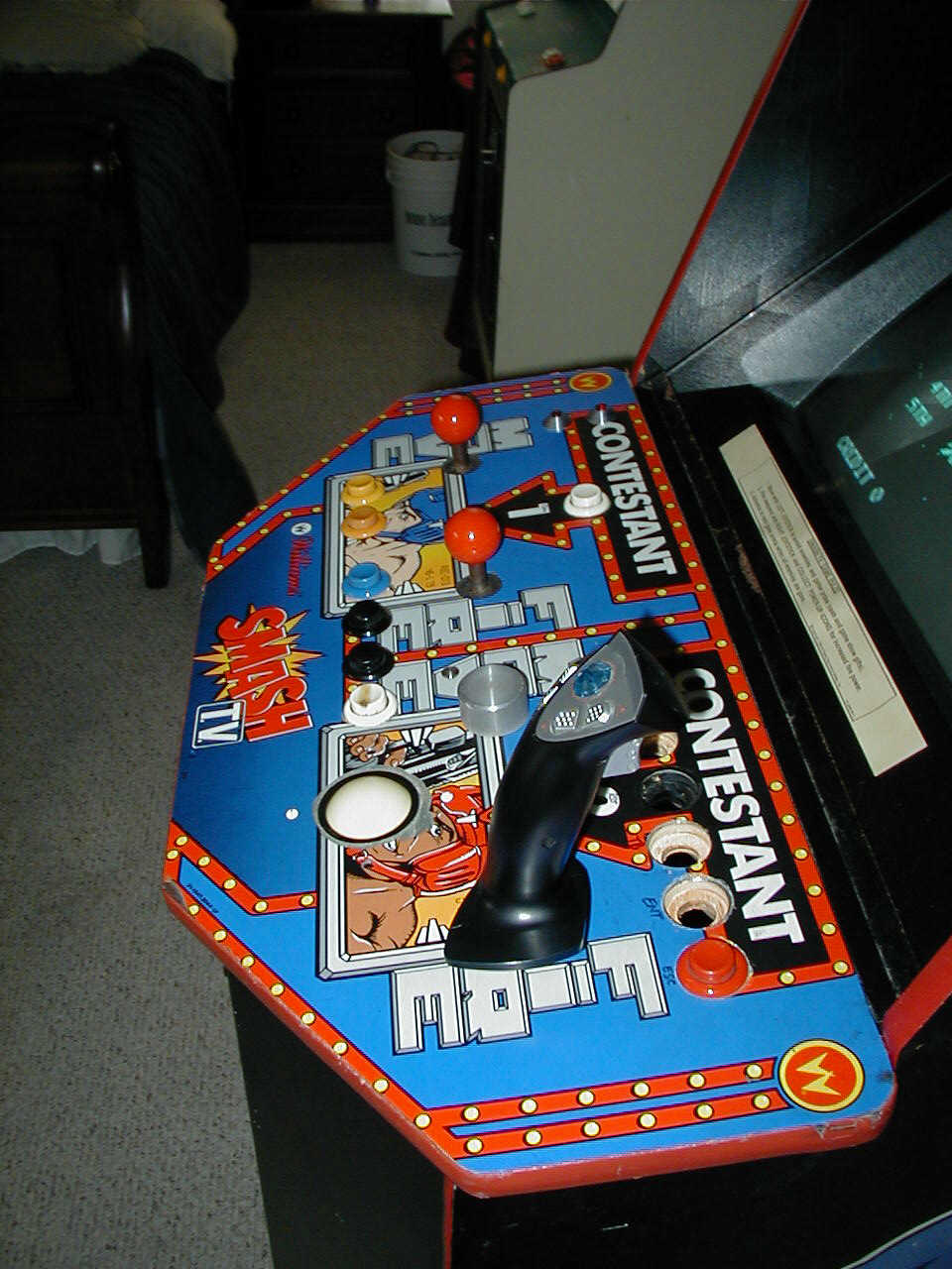
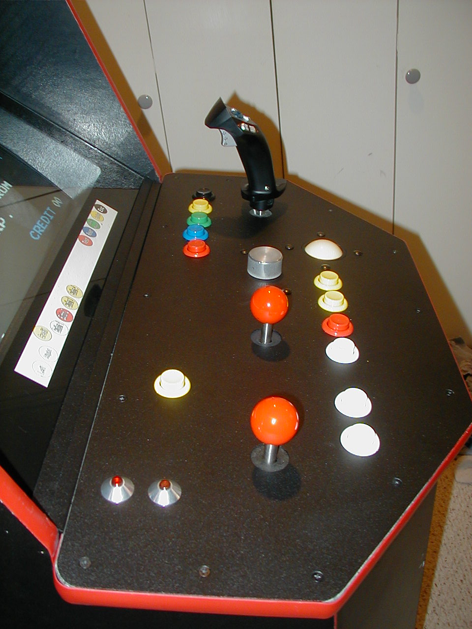
Here, you can see the general layout of the panel. The trigger joystick handle was placed on the panel to see what everything would look like.
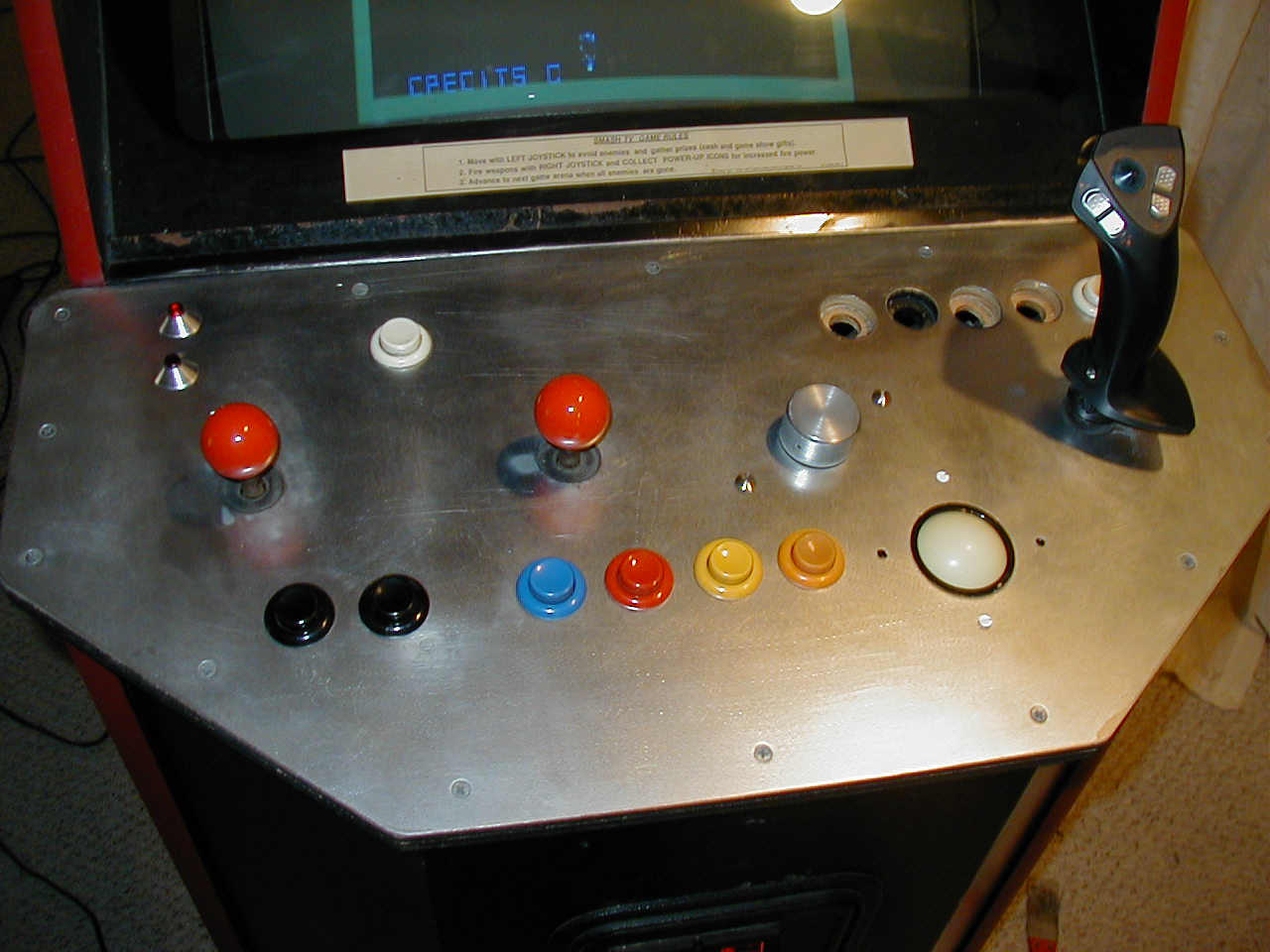
First, a 2 1/4" hole saw was used to cut the hole for the trackball. Then the mounting problem was solved using a small Makita circular panel saw, set to the depth of the wood but not so deep to hit the sheet metal mounted to the wood. Enough material was cut to allow the mounting of the spinner & trackball units.
To drill holes for short buttons, I first drilled on the topside with a 1 1/8" hole saw to only 1/4" depth. Then on the bottom side, using the pilot hole from the first step, I drilled using the same 1 1/8" hole saw to 1/16" depth to allow the pal nut to engage the threads of the button. To complete the hole, I used a 3/4", drilling from the bottom side. Usually, the topmost larger wood plug would come off with the 3/4" plug.
I also used the 1 1/8" hole saw to drill on the bottom side for the lighted start buttons, as they were metal mount switches.
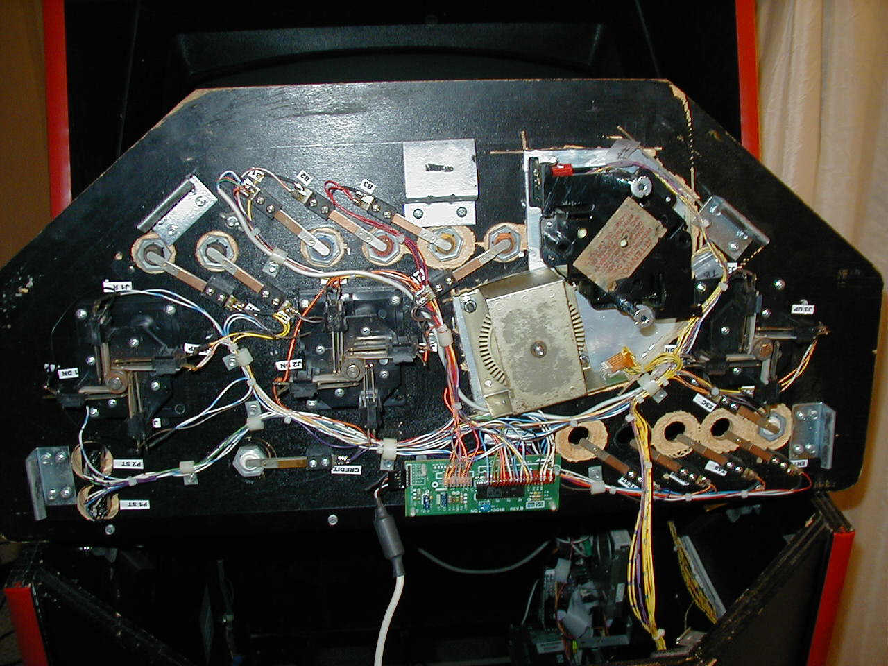
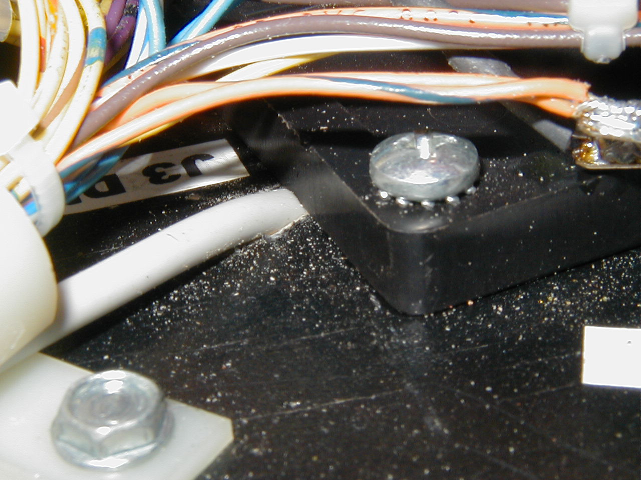
All the switches were wired up to a keyboard controller (Green PCB at bottom of panel) using diodes at each switch to prevent ghosting
The original shaft was just slightly smaller than the diameter of the sawed-off joystick shaft, so I used a Dremel tool to enlarge it slightly, until it could be tapped onto the metal joystick shaft. Then the trigger handle could be mounted to the larger plastic shaft. To keep the handle from twisting, I used epoxy in the centering rubber bushing. I will include details on how I got the trigger switch wire through to the other side of the panel at a later time.
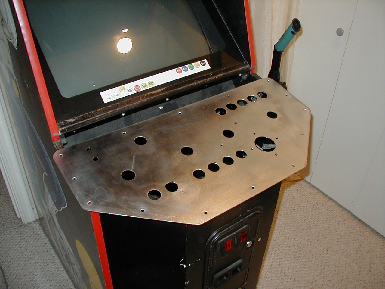
I then removed the Smash TV overlay, and sanded down to bare metal. I am looking into having an overlay made.
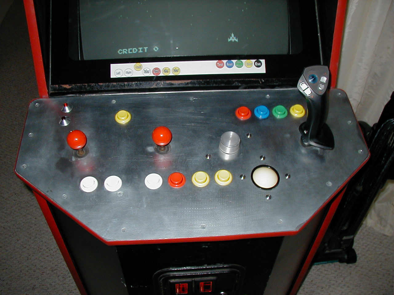
Finally, new T-Molding was installed, replacing the old. Looks great!
I should add, since I wanted to use an older version of Advance MAME (I had all the ROMS verified for version 0.56 of MAME), a problem I had with a lot of the games was getting an error message "Unable to start video emulation". There was very little information on the net about the root cause of this message, but one day, I decided to globalize some video settings (in the Video menu) and it seems to enable a lot more games to run.
The settings changed, then saved for all games are:
| 1. Magnify=ON | |
| 2. Resize=FRACTIONAL | |
| 3. Resize Effect=MAX |
UPDATE: 7/30/03
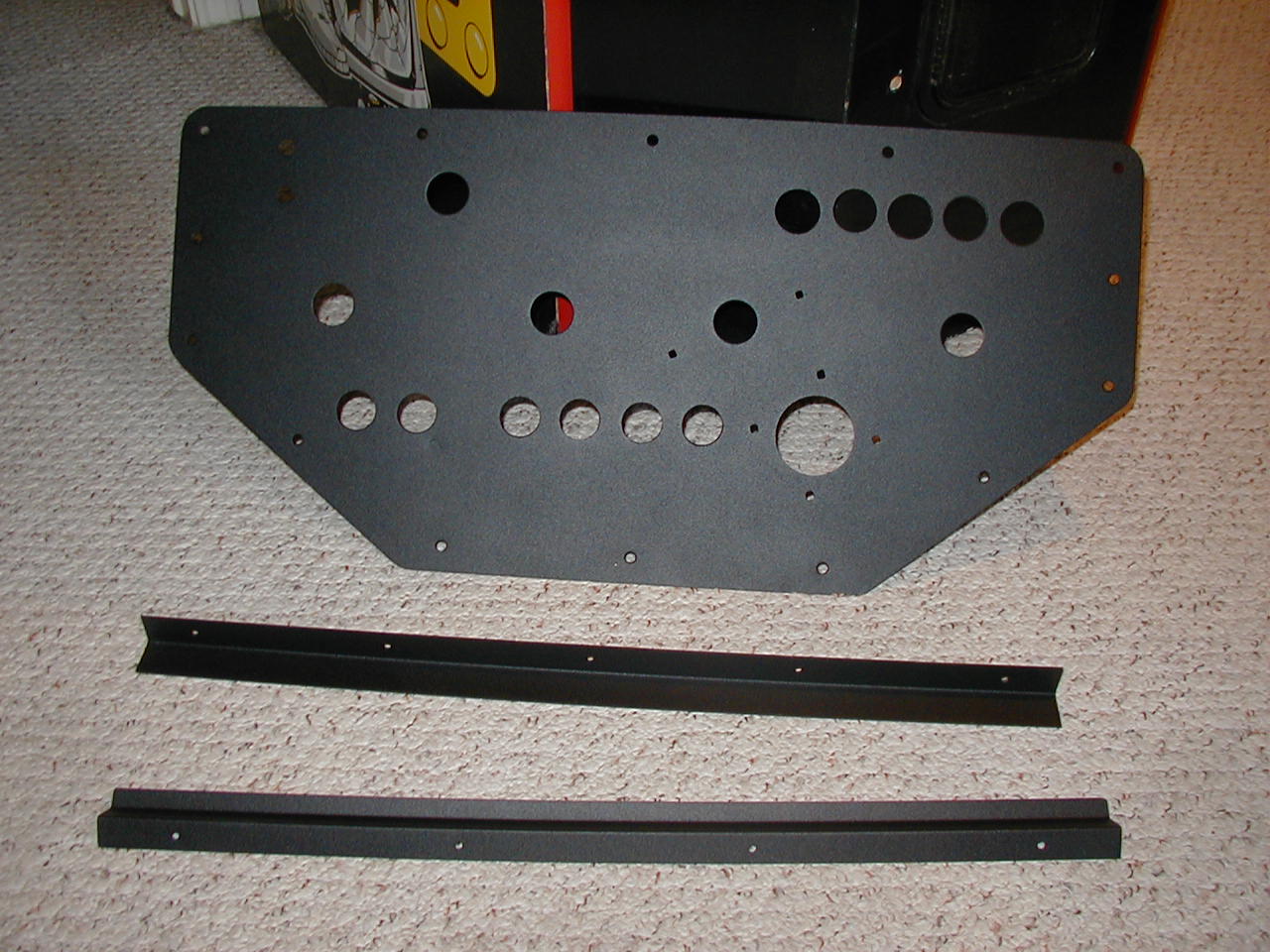
This Williams control panel is just sheet metal on top of 3/4" plywood. They had routed out an area for the plastic trim disc to ride between the two pieces, and screwed the Wico joysticks tot eh underside of the wood.
Given that there was not enough room to mount a standard trigger joystick, and I had decided to use the original joystick and modify it, it presented a couple of problems: How to get the trigger wire to the underside of the panel, and how to mount the plastic trigger handle to a standard red ball joy.
First I just cut off the red ball, and then I was going to have a machine shop bore out the center of the metal shaft that was remaining. Turns out that it would have been quite expensive to do, So I had to figure out another way.
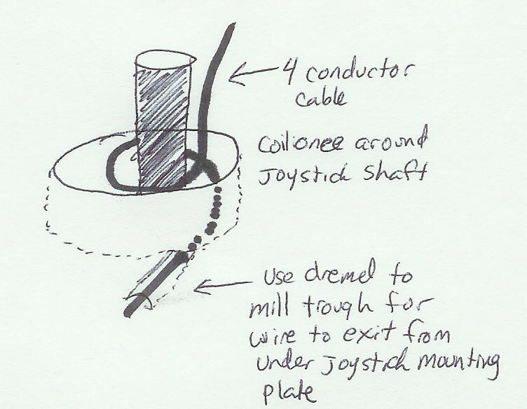
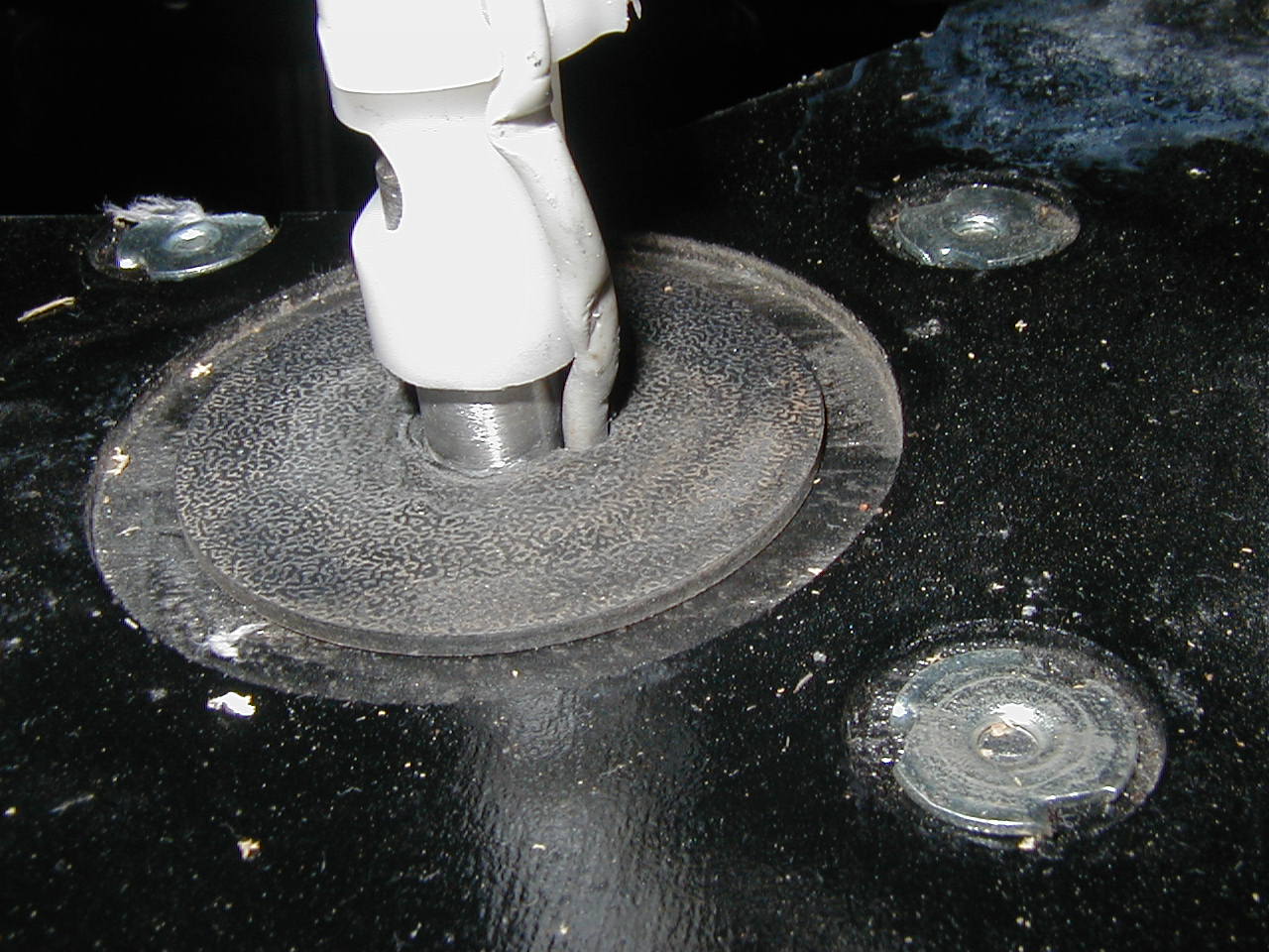
First, notch the plastic trim disc to allow the wire to pass thru.(the picture shows the damage that can be done to the wire when it gets misrouted in the handle, and was replaced) Then Dremel out a trough on the wood where the joystick mounts to the wood panel for the wire to exit there.
Insert a length of wire thru the panel hole, and line it up with the trough in the wood. Screw the joystick down. Now flip the panel over, and LOOSELY loop the wire at least one full turn around the shaft (it should be touching the wood more than the metal shaft). Then place the trim disc to that the wire exits and lines up with the back end of the shaft. The handle can the be screwed on after soldering the wires to the trigger switch.
Finished product as of 7/30/03